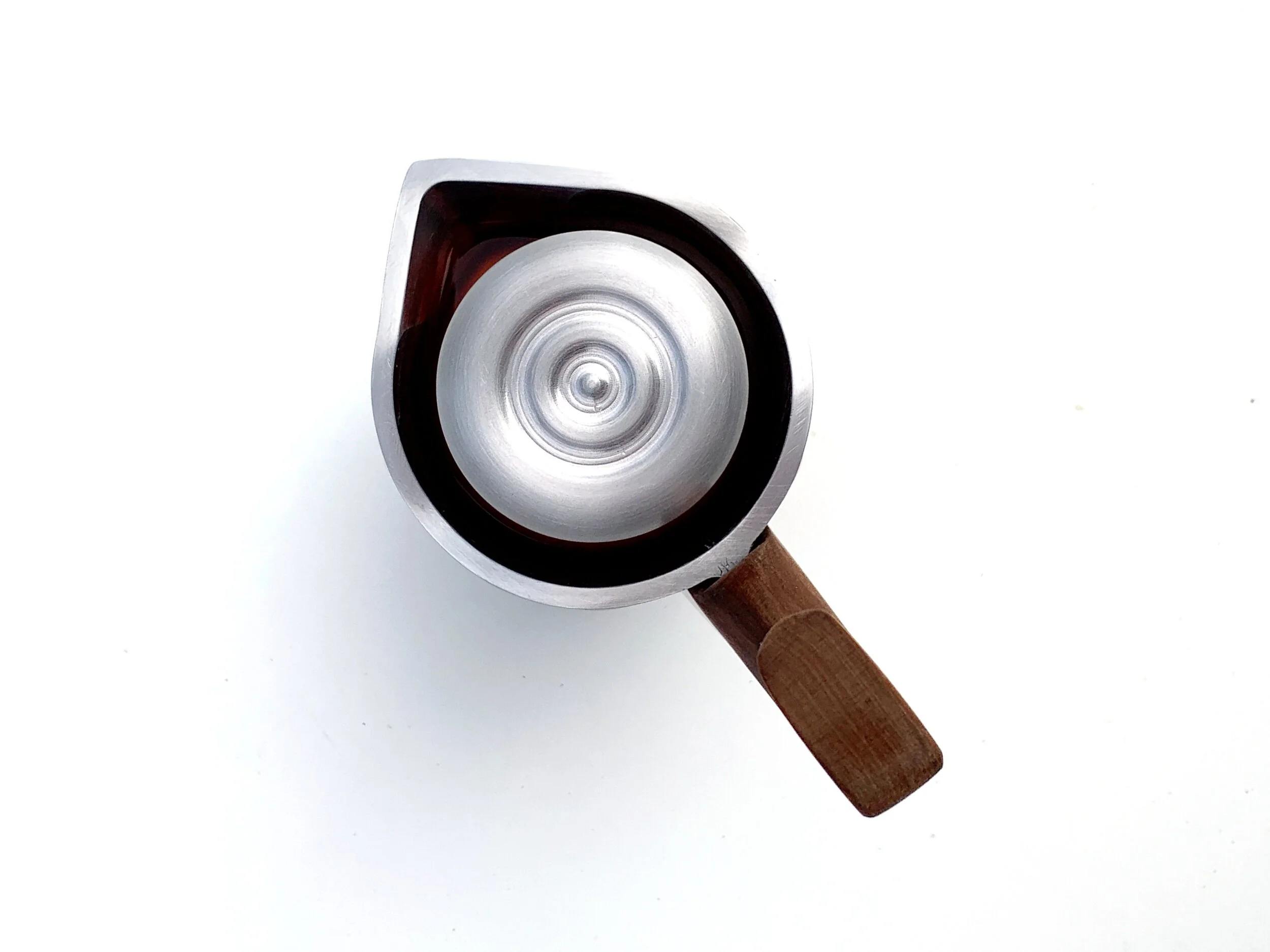
StoveTop Coffee Percolator - TeCHNICAL
Technical Areas of Focus: Finite Element Analysis, Manufacturing / Fabrication, Product Design
Project Length: 3 months
Participants: Matthew Derry
PERFORMANCE GOALS
The product aims to produce “moka-pot” style coffee at a higher pressure, producing roughly two shots of espresso. In standard coffee percolators, this process occurs at pressures of 1-2 bar, true espresso is produced at 8-9 bar of pressure. By CNC milling instead of casting these pieces along with reworking the fundamental geometry the design aims to achieve a higher pressure (4-5 bar) and thus, a stronger, richer cup of coffee.
HOW PERCOLATION WORKS
In order to achieve the necessary pressure in the lower reservoir, the product is heated on a stovetop. As the pressure increases the water is forced through the coffee grounds.
TECHNICAL IDEATION
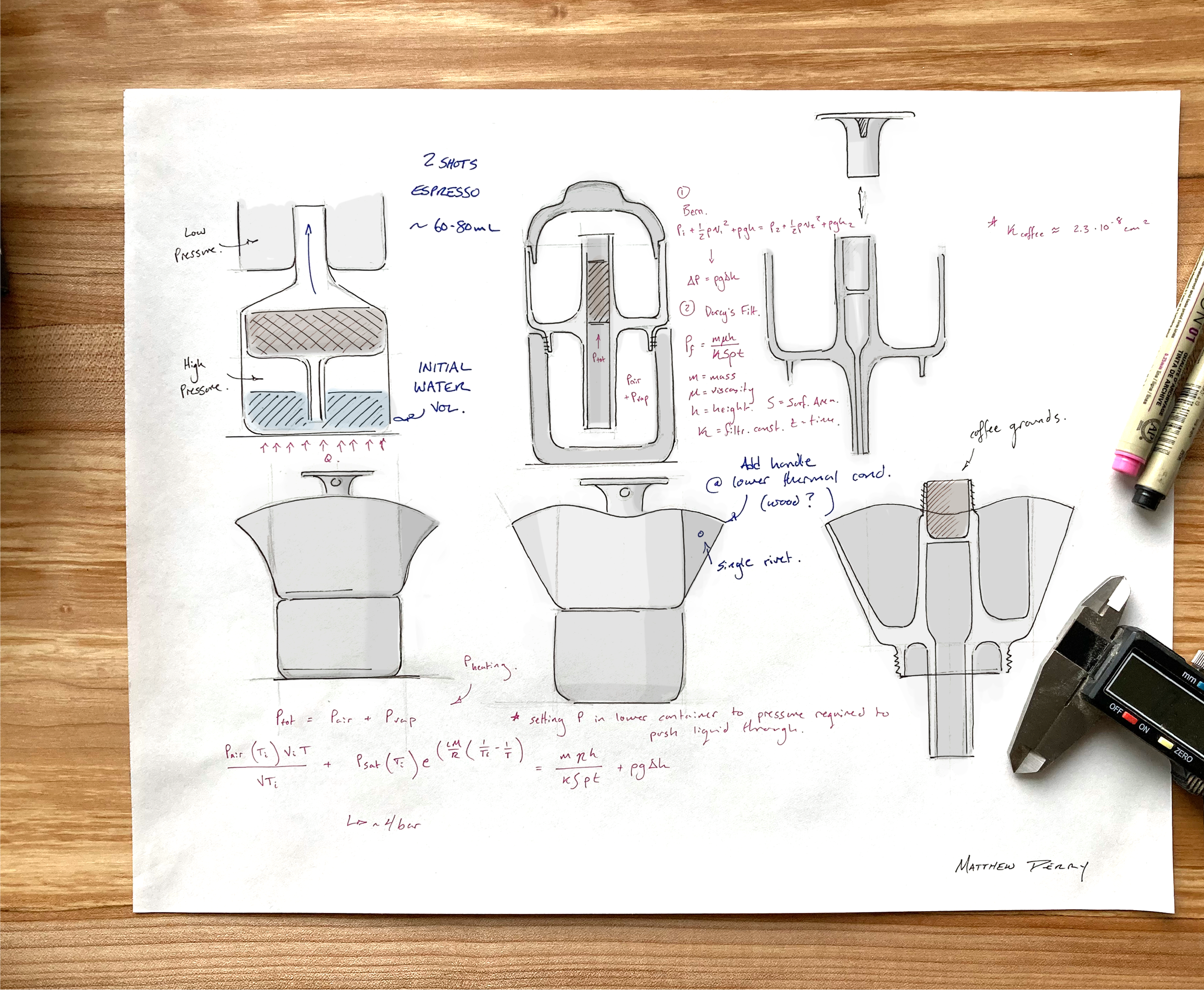
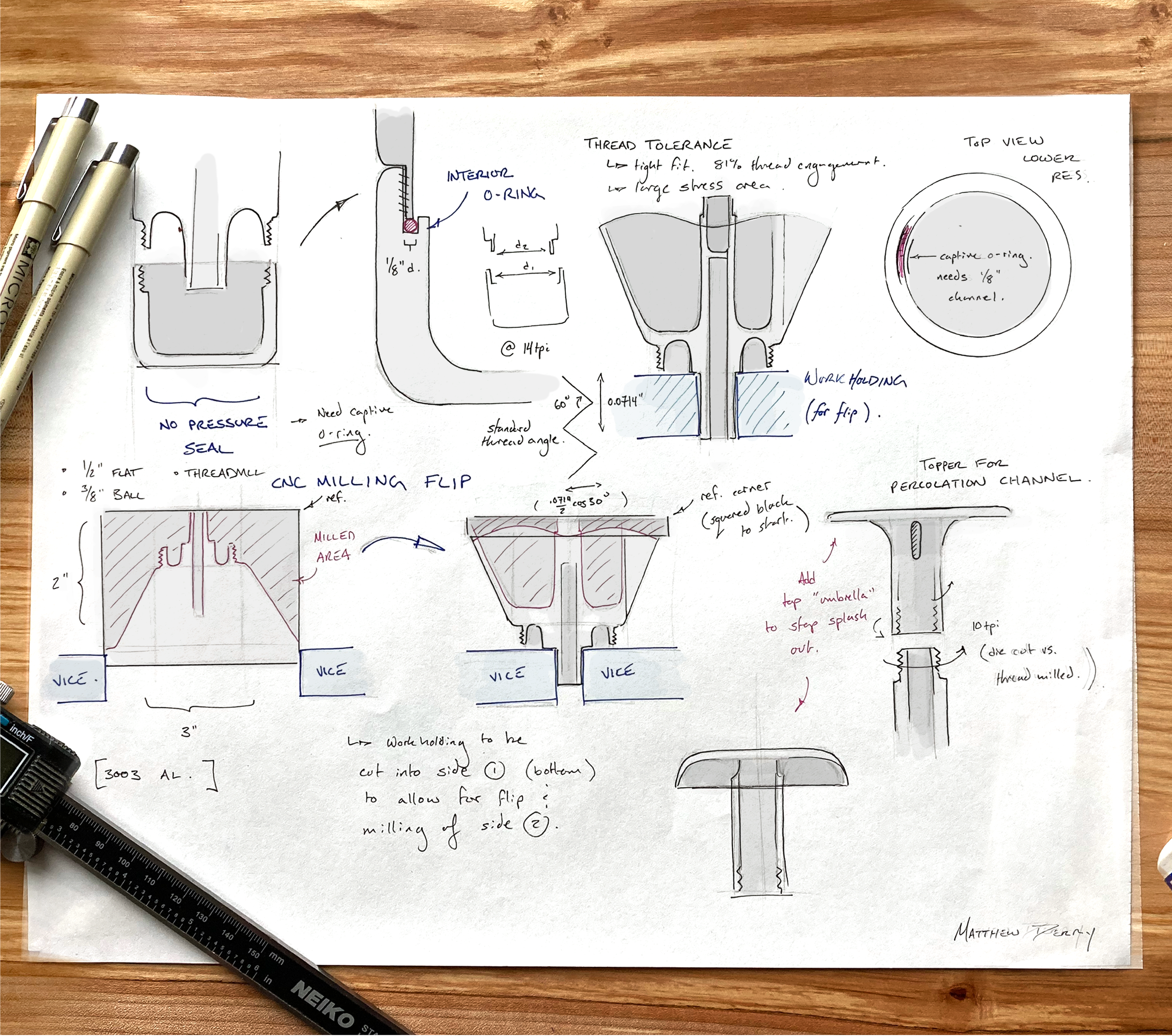
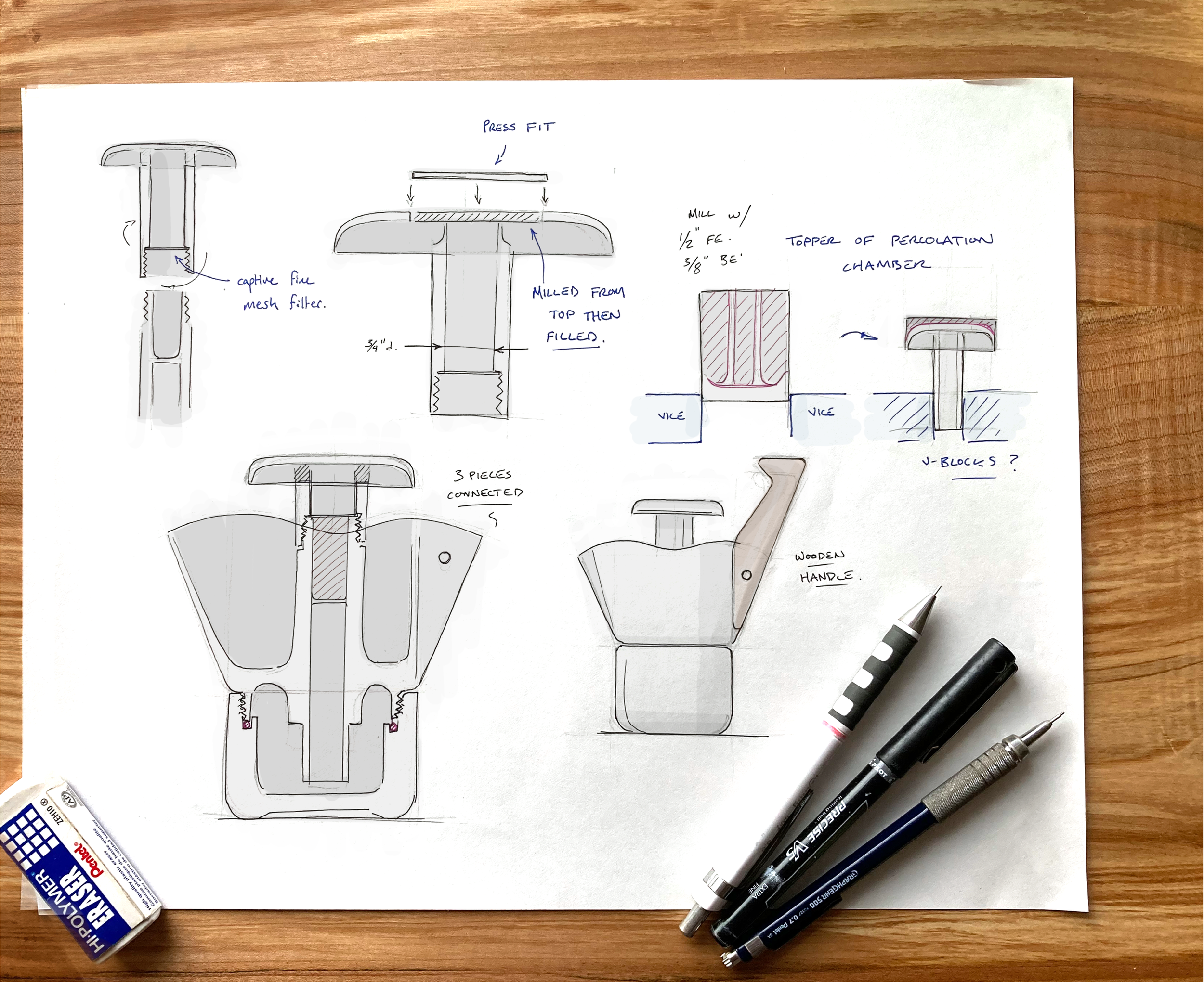
Sketching out how to solve the technical and manufacturing challenges that this project presented.
Theoretical Calculations & Simulations
Desired pressure for filtration: 4-5 bar
Final temperature of coffee: 368 K
Volume of coffee produced: (2 shots) -70-80 ml
The ideal dimensions for the puck of coffee grounds must be found to match the ideal-condition parameters. The desired pressure was based off of feasible pressure produced by heating of the bottom reservoir. The aim was to increase the pressure from the 1-2 bar that a standard "moka pot" style coffee percolator achieves to 4-5 bar, closer to the values used to brew "authentic" espresso.
EQUATING INTERNAL PRESSURE TO THE PRESSURE NEEDED TO PERCOLATE COFFEE:
To achieve a more accurate value for the pressure, the internal pressure of the bottom reservoir was matched to the pressure needed to push liquid up the central channel + the pressure needed for the liquid to filter through the coffee grounds see Equation ( 1 ).
CALCULATION OF INTERNAL PRESSURE (from air pressure and vapor pressure) INSIDE THE BOTTOM RESERVOIR WHILE HEATING:
The internal pressure of the reservoir has contributions from attempted expansion of the air pockets trapped above the water and the vapor pressure caused by the heating of the water (see Equation ( 2 )). Both of these factors are dependent on the temperature (T). The final temperature was set to 95 degrees Celsius later in the calculations to match ideal values for coffee brewing.
PRESSURE DUE TO HEATING OF TRAPPED AIR:
For the pressure from the attempted expansion of air, I used a modified ideal gas equation (Equation ( 3 )) as a reasonable approximation. The initial and final volumes are roughly equal as we are just looking to find the pressure when filtration begins. Overtime, the water level will decrease, and thus this partial pressure will decrease (as the final volume of the air grows).
PRESSURE DUE TO WATER VAPOR FORMATION:
Similarly we find the partial pressure from the saturated water vapor at a given temperature using Equation ( 4 ). This equation is derived from the Clausius Clapeyron equation which assumes that the vapor will perform as an ideal gas. This is a somewhat inaccurate simplification at high temperatures. However, within the range we are concerned by, it should give a reasonable estimation.
COMBINE FOR TOTAL INTERNAL PRESSURE:
Combining Equations ( 3) and ( 4) gives us the estimated pressure inside the bottom reservoir. Using dimensions from the Solidworks model and given values for the saturated vapor pressure of water, and the variables L, M, and R we find the total pressure is 4.3 bar, nicely within the desired range.
Internal pressure when filtration should begin: 4.3 bar.
PRESSURE AGAINST GRAVITY:
With this internal pressure to work from I solved for the other half of Equation ( 1 ) which combines the filtration pressure and the pressure needed to overcome the difference in elevation. Using an idealized Bernoulli Equation I found the expected pressure just to overcome the height difference (see Equation (5)). This ended up being less than 1 kPa (substantially less than the pressures achieved within the bottom reservoir).
FILTRATION PRESSURE:
This means that the bulk of the right hand side of Equation ( 1 ) is due to the pressure required to push the fluid through the filtration puck of coffee grounds. The equation for this pressure was estimated with Darcy's Law for linear filtration (see Equation ( 6 )). This equation requires the filtration constant (k) for coffee grounds, I used a value derived by Concetta Gianino (see references at the bottom of the page) for a "moka" style coffee pot. This value will change based on whether the coffee grounds are packed in, the fineness of the grind etc. however, having a value to work from will keep the design inside a functional range.
SOLVE FOR UNKNOWN DIMENSIONS:
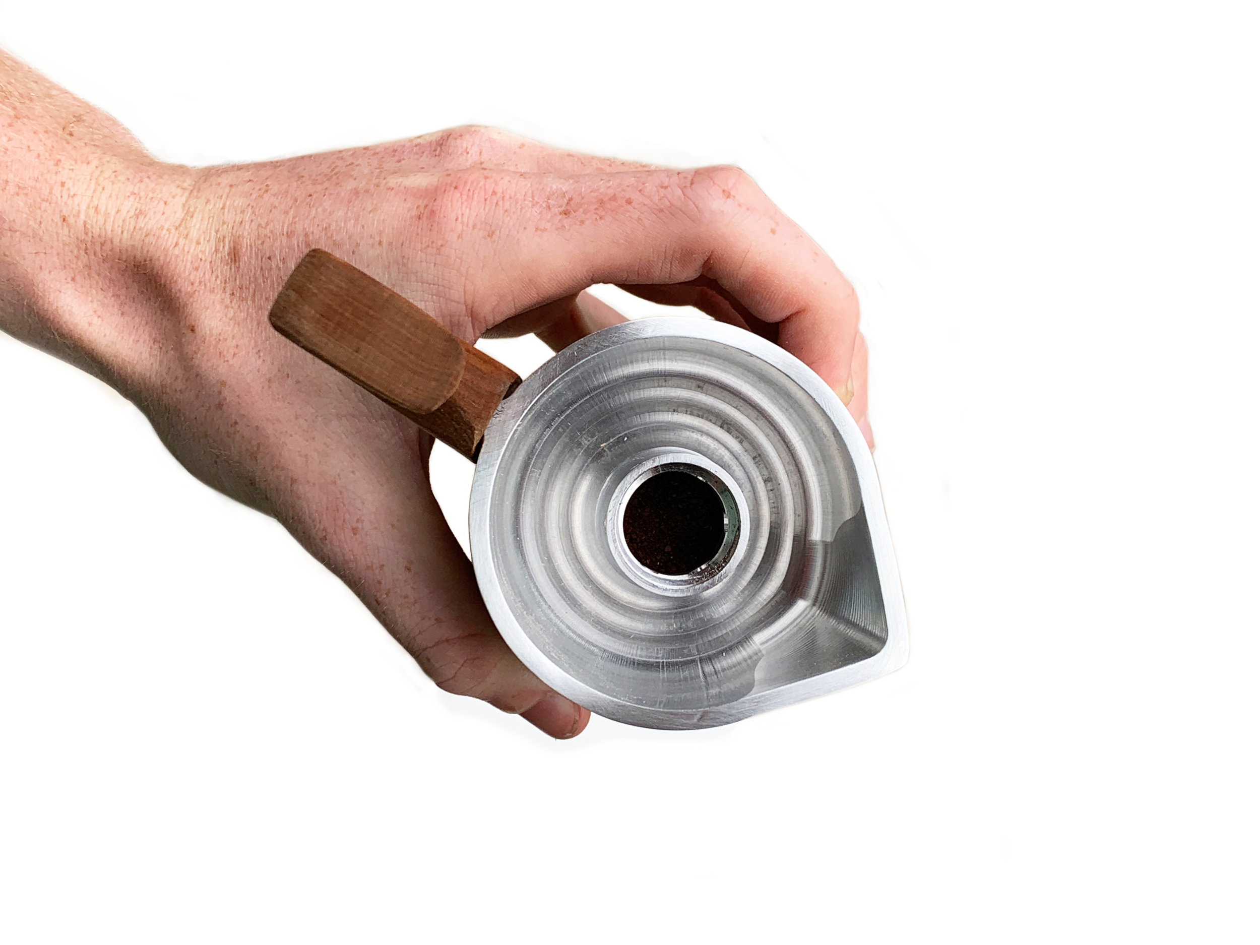
Thus, equating the internal pressure of 4.3 bar to the pressure needed to overcome height gain and the pressure required for filtration it was possible to solve for h, the height of the coffee ground puck. This turned out to be 1.25"for a surface area of pi/4 square inches (the filtration area).
TAKEAWAYS:
This analysis resulted in the dimensions of coffee grounds area (height = 1.5”, diameter = 1”) and the theoretical maximum pressure inside the bottom reservoir to be 4.3 bar.
STRESS, STRAIN, & HEAT TRANSFER SIMULATIONS:
With the dimensions set and the maximum internal pressure found, I combined the effects of the thermal load with an internal pressure of 4.3 bar and ran force, stress, and displacement analyses through Solidwork’s simulation software (see images below). This led me to fillet all the corners I could to reduce stress concentrations and ensured that the pressure induced would not lead to failure in any of the components. These simulations assume the o-ring creates a perfect pressure seal and that the threaded connection does not reach failure. Additionally the coffee grounds are taken to be an impermeable layer before the pressure passes 4.3 bar.
Stress due to 4.3 bar pressure
Displacement due to 4.3 bar pressure (visual displacement exaggerated by x 500)
The ideal heat of water for coffee filtration is ~95 degrees Celsius which is achieved within the first 2 minutes of heating on a stovetop surface (determined through Solidworks simulation). Running these analyses helped to define the thickness and geometric form for the bottom of the lower reservoir. Even though it resulted in a less efficient heating method, the final design has a slightly concave bottom so it will sit on surfaces more easily and ensure that small displacements will not effect its stability.
FINAL DESIGN
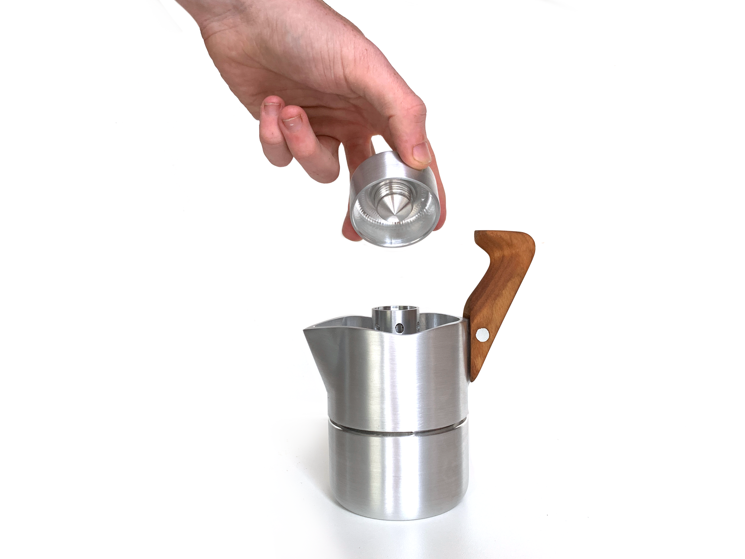
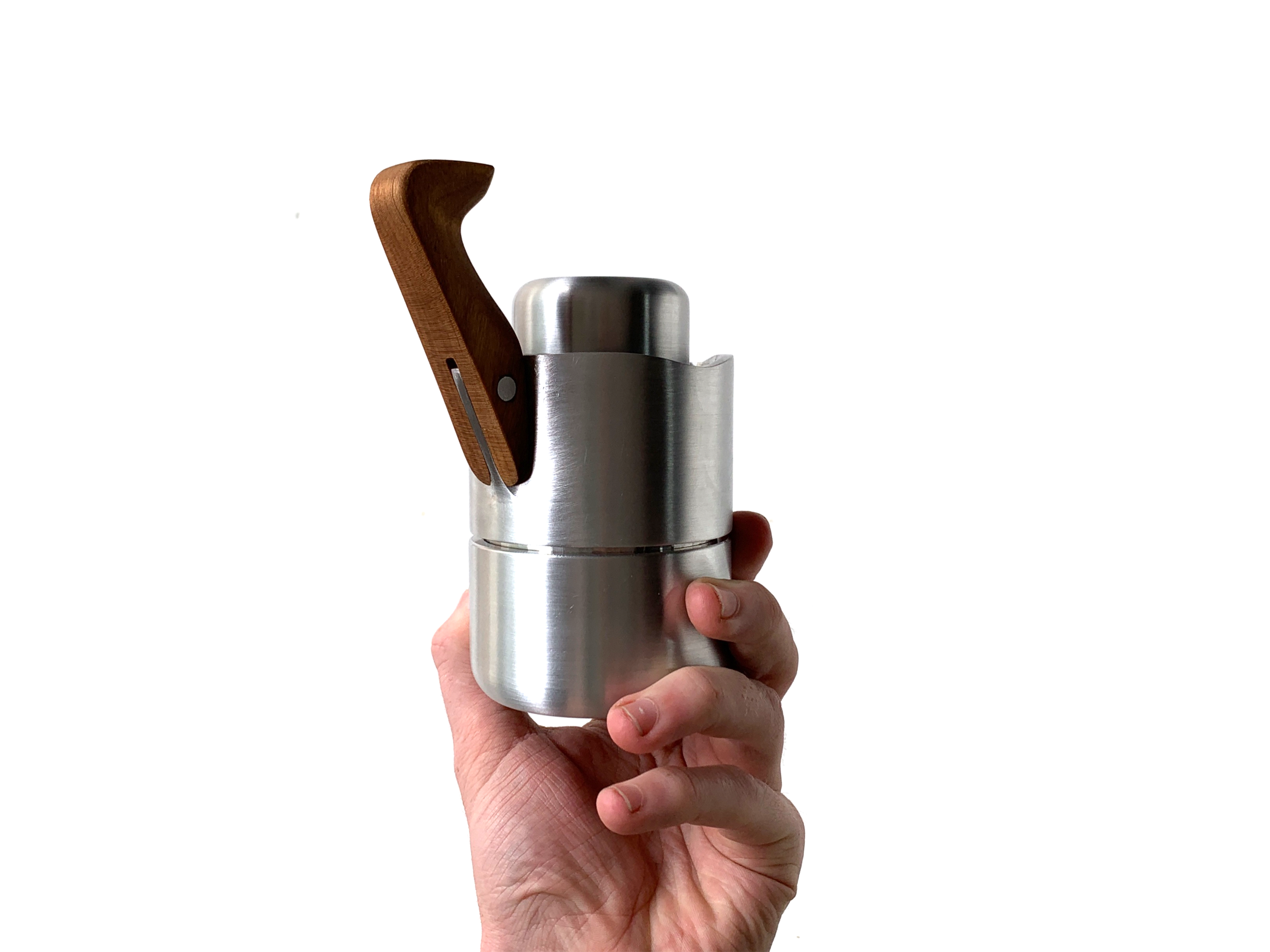
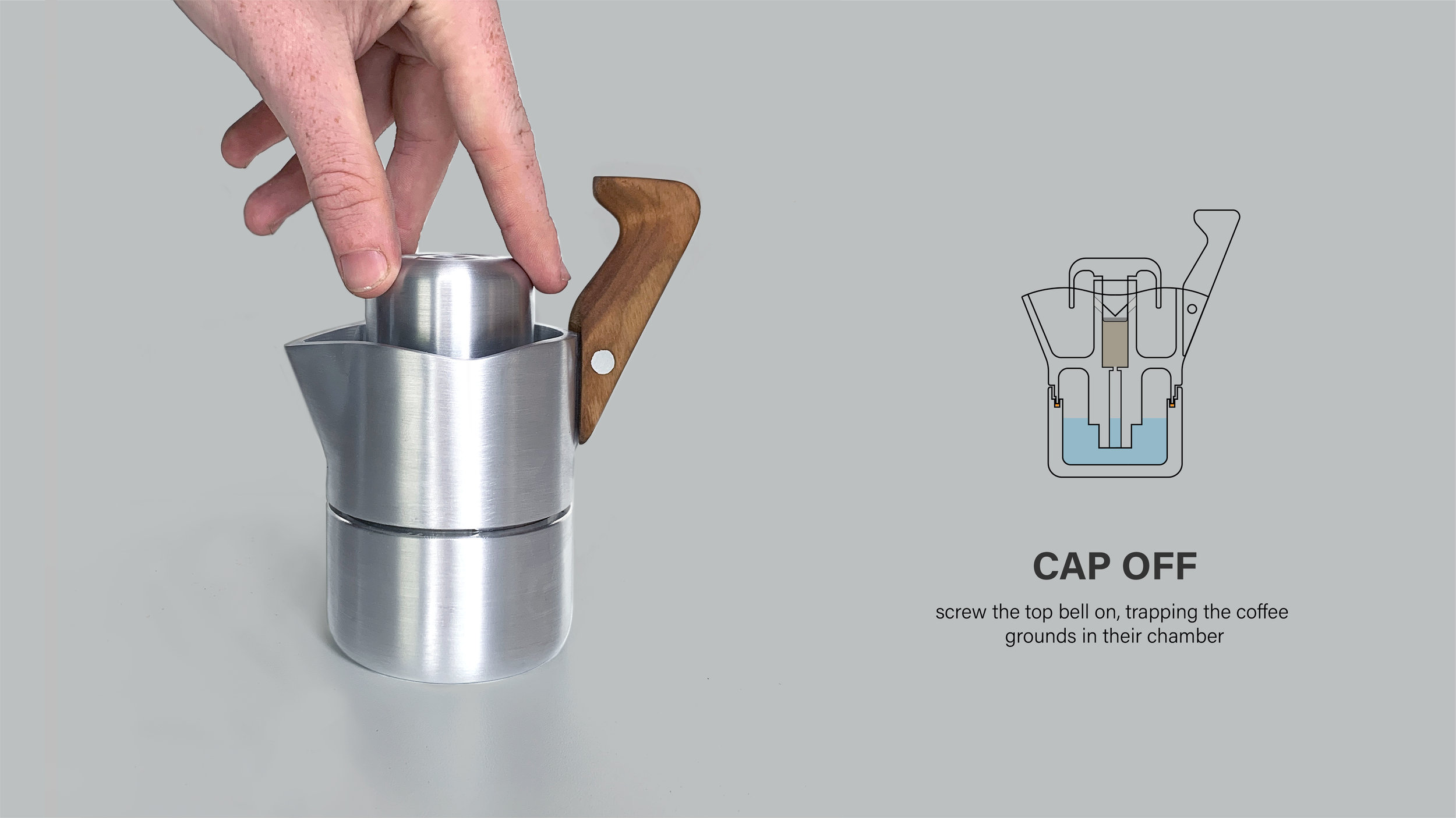
HOW TO USE - STEP BY STEP
FABRICATION - CNC MILLING
The final model was built using Solidworks then the toolpaths were designed using a HSMworks plugin. Everything was machined from a 3” x 5” and a 2” x 2” block of 3003 Aluminum.
MACHINED DETAILS
